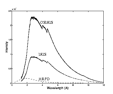
Flux comparison. between OSIRIS, IRIS and HRPD. .
ISIS is not a continuous source of neutrons, as is a nuclear reactor. Neutrons are produced in pulses by letting a burst of protons hit a target (at present tantalum) where by neutrons are produced by spallation. At ISIS, neutrons are produced every 20000\mus (ie with a frequency of 50Hz). The neutrons released are however far to fast/hot and have to be slowed/cooled down. This is done in a moderator. Around the target there are different moderators at different temperatures. The OSIRIS guide is directed towards the H2 moderator at 22K. This means that the Maxwellian distributions of velocities/wavelengths has its maximum around 6Å. The actual maximum is slightly lower, since there also exists a wing from the high energy (low wave-length) epithermal neutrons which moves the maximum to lower wave lengths, see fig. intfig.

Flux comparison. between OSIRIS, IRIS and HRPD.
.
In fig. intfig we compare the neutron flux at OSIRIS, IRIS and HRPD. Expect from the fact that the flux is much higher at OSIRIS there is now big difference between it and IRIS. The flux on HRPD though much lower extends to much lower wavelength. This diffractometer is directed towards the hotter CH2 moderator at 100K, which gives a maximum around 2.5Å.
Another difference between the two instruments regarding incident neutrons is that OSIRIS has a curved super-mirror guide, that will not transmit neutrons below ca 1Å, where as this is not the case for HRPD. The curved guide decreases the background from high energy neutrons but limits the lower d-spacing range attainable at OSIRIS to ca 0.7Å. As you understand from fig. intfig, OSIRIS is focused on the long wavelength part of the diffractogramme.
Both OSIRIS and IRIS, the instrument next to OSIRIS, have the same main shutter (N6) and look at the same moderator. OSIRIS, however has a curved super-mirror guide made of NiTi it is 65×43 mm, though just before the sample, there is a piece of converging guide and after that part the beam is 44×22 mm.
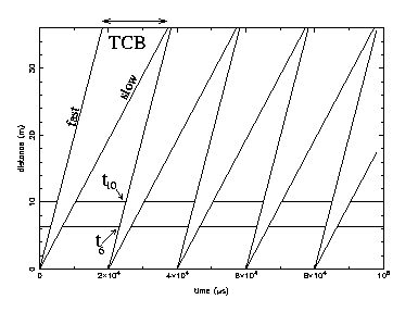
If we were to let all the neutrons in one pulse hit the sample, some of the slowest neutrons of pulse 1 would not reach the detectors before the fastest neutrons of pulse 2 did, and we would have no way of telling them apart. We need to pick out a small wavelength band of neutrons. On OSIRIS we use two choppers to "cut" a slice, of the full wavelength distribution, such that the time spread when they arrive at the detectors is no larger than that of one pulse, ie 20000\mus, it is possible to run the choppers at an integral fraction of the ISIS (50Hz) and thereby create a longer window for counting the neutrons.
In fig. chopfig a time distance plot of 5 ISIS neutron pulses are shown, one pulse every 20000\mus. The choppers are marked by the two horizontal lines, on at 6.3 (opening angle 60 deg) and one at 10m (opening angle 100 deg). This gives a bandwidth of about 2Å at 50Hz and 4Å at 25Hz. The choppers are opened where the line is broken. The opening time for the 6m chopper t6 and the 10m one t10 is shown for the second pulse. The line marking the fastest neutrons (shortest wavelength) let through is marked fast and the corresponding one for the slowest neutrons (longest wavelength) is marked slow.
You note how, when the neutrons reach the detectors at 35 meters, they have spread out in time, but they do not overlap with the next pulse. The times at which the fastest and slowest neutrons reach the detectors define the boundaries between which the computer should count one frame, these times then define the Time Channel Boundaries (TCB). If we were to measure slight faster neutrons the TCB's in fig. chopfig would shift to the right. For every chopper setting there is a corresponding set of TCB's.
There are already a set of wavelength ranges and their corresponding TCB's calculated for OSIRIS, so here we just go through a simplified way of how to calculate the phases and TCB's. To decide the phase of the choppers we start by deciding the shortest wavelength to pass the first chopper. These are the first neutrons we want to pass, all the rest have longer wave lengths and are therefore slower. The first chopper is opened when these neutrons reach the chopper. To calculate the time at which these neutrons reach the chopper, since neutrons can be treated as classical particles, we use the simple formula:
where c1=252.78, the time [t]=\mus, the wavelength of the neutrons [\lambda]=Å and the distance from the moderator to the chopper [L]=m.
Assume we want to look at a d-spacing larger than 10Å. We decide to
use the highest resolution, the highest scattering angle,
almost 180 degrees (actually 171). This means with
The last thing we have to do is to tell the computer between what times after the neutron pulse it should count, ie calculate the TCB's. The first neutrons hit the detectors at 34+1 meters at t=c1×35×20=176946=177000, from the opening angle of the choppers we can also calculate the slowest neutrons to arrive, see fig. chopfig, and we could set this to be the high limit of the TCB but in practice, after making sure that we have no frame overlap, we set the width of the TCB to be one pulse long, ie 20000 \mus.
|
Wavelength | Chopper | TCB |
| 2-6Å | 3180,5056 | 13000-53000 |
| 4-8Å | 6370,10100 | 28000-68000 |
| 6-10.4Å | 9555, 15150 | 45500-85500 |
| 8-12Å | 12740,20200 | 63200-103200 |
| 10-14Å | 15900,25250 | 80000-120000 |
| 12-16Å | 19100,31750 | 100800-140800 |
| 14-18Å | 22250,36700 | 117800-157800 |
| 16-20Å | 25450,1790 | 136000-176000 |
| 18-22Å | 28665,6845 | 152000-192000 |
| 20-24Å | 31850,11900 | 170000-210000 |
| 22-26Å | 35035,16955 | 186000-226000
|
The monitors are glass bead monitors. There are five beads horizontally and
6 vertically. The active component is 6Lithium.
The calculated efficiency of the monitor is
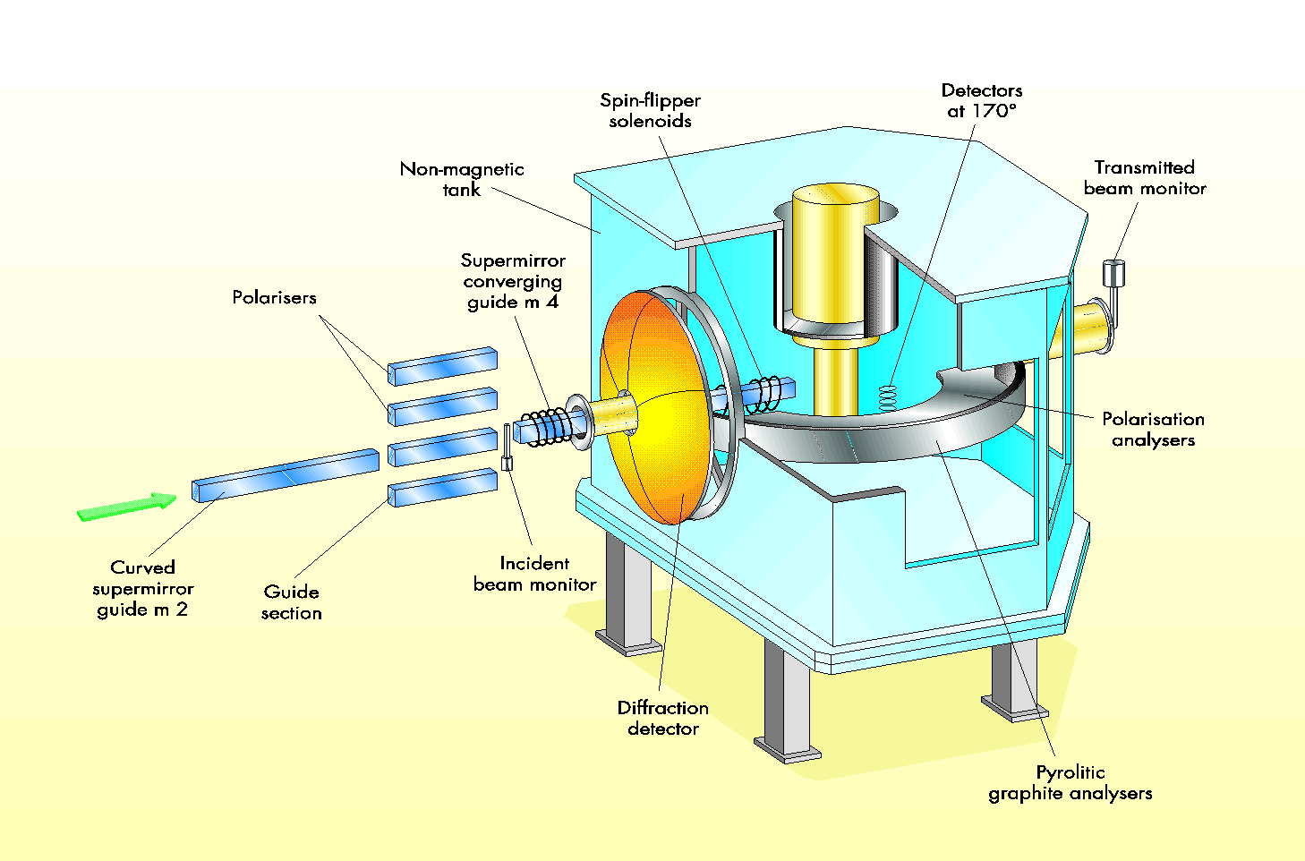
Figure: The artists view of the OSIRIS spectrometer.
At present the operative part is the diffractometer, see text.
/caption>
In fig. osifig you see an artists view of OSIRIS. From the left: the curved super-mirror guide (the choppers are further left); polariser, only used for testing now; incident beam monitor; converging guide; and then the neutrons are backscattered from the sample into the diffraction detector bank.
The detectors are Scintilators and the full detector bank contain 8 modules, whereof 3 are at present operative, see fig. bankfig. The further 5 modules are being put in place as they are delivered. Each module contains 120 scintilator elements, see fig. enmodulfig. The first 20 are single detectors. Between 21 and 120 the even numbered detectors are still single ones but the odd numbered are physically composed of one detector above and one below the even ones, see fig. enmodulfig. The detectors are numbered sequentially starting at number 3 (the first two spectra are the monitors). Module 1 is 3-122, module 2 is 123-242 and module 3 is 243 to 362. As a user you will most often not use these number but refer to the first 20 in all modules as "high" resolution and all detectors as "all".
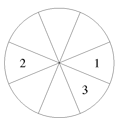
Figure: The layout of the OSIRIS diffraction detectors, view from the
sample position. At present there are three modules of eight in
place.
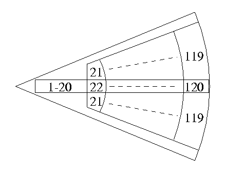
Figure: The layout of the one detector module (not to scale). The first twenty detectors are single detectors, there after the odd
numbered detectors actually are composed of two couple detectors.
As standard one measures from d=0.7Å up to about 10Å. The lower limit is fixed by the fact that there are no neutrons of low enough wavelength to be diffracted. The higher limit is not a real limit however. d-spacings up to 30Å have been measured. It is appreciated if the user makes clear before the experiment if he wants to measure d-spacings large than 10Å. To choose the adequate measuring time one has to realise that as the incoming intensity decreases for higher wavelength the scattering increases as \lambda
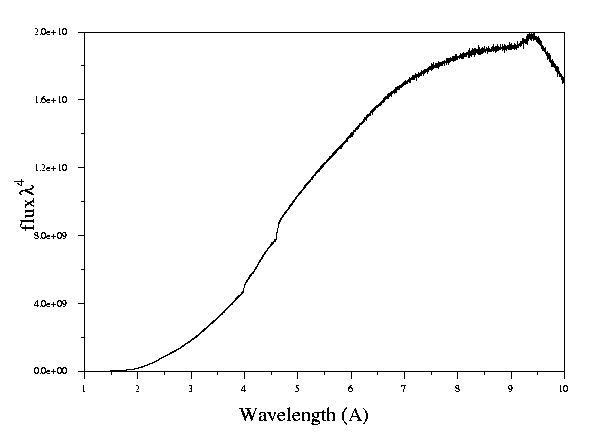
Figure: Flux times wavelength to the 4th. Since Bragg scattering
increases with the fourth power of the wavelength the
flux is in this figure multiplied by the wavelength to
the fourth.
This is a short summary of some of the sample equipment that has been used on OSIRIS, for a full description of the equipment mentioned here and much more see the SE-miniguide on the web page of the SE-group here.
This is of course the simplest experiment to do your sample is screwed on to a center stick, put in the sample tank, which is then evacuated.
There are two cryostats normally used on OSIRIS, the older orange/ILL and the newer blue/Oxford Instruments one. They are both helium cryostats and can reach down to 1.5K when pumped on. There is a choice between 100 and 50 mm bore for the orange one (the blue is 50) and Vanadium or Aluminium windows (blue has Aluminium).
The RAL furnaces can reach a temperature of 1200 degrees and they come with sample space between 32 and 65 mm. There is also a cryo furnace which can reach temperatures from 1.5 to 600K.
The cry-magnet can achieve fields up to 7.5 T and temperatures from 2 to 300K.
Various pressure cells can be used depending on what pressure you want to reach, see the SE-miniguide for further info.